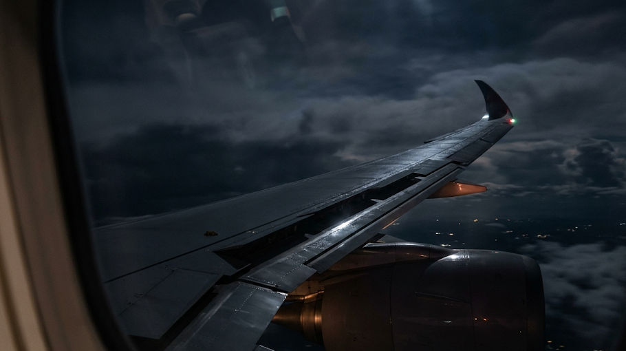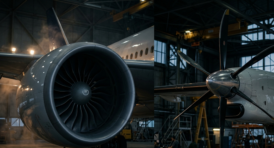
The structural airframe architecture of modern commercial transport aircraft has undergone an unprecedented material revolution. While twentieth-century aircraft were constructed predominantly from riveted aluminum alloys (Al 2024 and 7075), state-of-the-art airliners—exemplified by the Boeing 787 Dreamliner and Airbus A350 XWB—feature airframes comprising over 50% to 53% advanced Carbon-Fiber Reinforced Polymer (CFRP) Composites by weight. Fabricating primary load-bearing structures—such as one-piece fuselage barrel sections and monolithic 32-meter wingboxes—from carbon fiber delivers massive weight savings, eliminates atmospheric corrosion, and extends airframe fatigue inspection thresholds by over 50%.
Unlike isotropic metals whose mechanical properties (elastic modulus $E$, yield strength $\sigma_y$) are identical in all spatial directions, carbon-fiber composites are strongly Anisotropic / Orthotropic. Unidirectional carbon-fiber tape possesses immense tensile strength along the fiber longitudinal direction ($E_{11} > 150 \text{ to } 180 \text{ GPa}$, $\sigma_{11,ult} > 2,500 \text{ MPa}$), but possesses weak transverse properties dominated by the brittle polymer matrix ($E_{22} \approx 10 \text{ GPa}$). Aerospace structural engineers exploit this anisotropy by tailoring fiber layups to match principal aircraft stress trajectories precisely.
Classical Laminate Theory (CLT): The ABD Stiffness Constitutive Matrix
The mathematical analysis of multi-ply composite aerostructures relies on Classical Laminate Theory (CLT). An aircraft skin laminate comprises multiple plies of unidirectional prepreg tape stacked at tailored fiber orientations (typically standardized combinations of 0°, ±45°, and 90° plies).
Under CLT, the constitutive relations coupling in-plane forces ($N$) and bending moments ($M$) to mid-plane strains ($\epsilon^0$) and curvatures ($\kappa$) are formulated via the fundamental ABD Matrix:
[ N / M ] = [ A B ; B D ] * [ ε0 / κ ]
- Extensional Stiffness Matrix ($A_{ij}$): Dictates direct in-plane tensile and shear stiffness ($A_{ij} = \sum Q_{ij}^k \Delta z_k$).
- Coupling Matrix ($B_{ij}$): Represents coupling between in-plane membrane forces and out-of-plane bending. In aerospace design, laminates are strictly engineered to be Symmetric ($B_{ij} = 0$) to prevent thermal warping during autoclave cool-down.
- Bending Stiffness Matrix ($D_{ij}$): Dictates flexural and torsional rigidity of the wing skin.
Automated Fiber Placement (AFP) and Autoclave Polymerization Mechanics
Primary composite aerostructures are manufactured using multi-axis robotic Automated Fiber Placement (AFP) machines. Robotic placement heads steer 16 to 32 parallel narrow strips of carbon-fiber prepreg tape (tows) onto contoured invar tooling mandrels at speeds exceeding 1.0 meter per second, heating the tape with infrared or diode lasers to tack plies securely without fiber wrinkling.
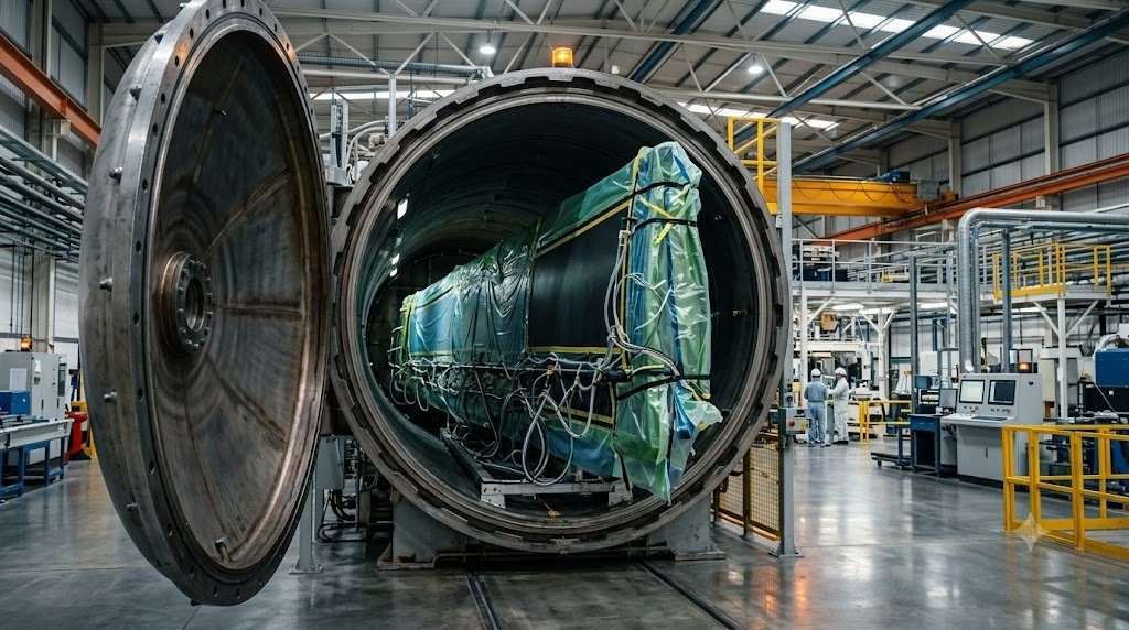
Following layup, the component is vacuum-bagged and loaded into a massive industrial Autoclave (such as the 9-meter diameter pressure vessels used for 787 fuselage barrels). The autoclave subjects the part to 0.7 MPa (100 psi) of hydrostatic nitrogen pressure and ramps temperature to 180°C (355°F). Elevated pressure collapses microscopic inter-ply void pores, consolidating the laminate to a void content of $< 0.5\%$, while thermal activation triggers irreversible chemical cross-linking of the epoxy resin matrix.
| Aerospace Structural Material | Density (ρ in g/cm³) | Specific Tensile Modulus (E/ρ) | Corrosion Susceptibility | Fatigue Resistance (S-N Curve) |
|---|---|---|---|---|
| Aviation Aluminum 2024-T3 | 2.78 g/cm³ | 26.3 GPa·cm³/g | High (Galvanic / Exfoliation) | Susceptible to Cyclic Metal Fatigue |
| Aluminum-Lithium 2195 | 2.71 g/cm³ | 28.5 GPa·cm³/g | Moderate | Improved Fatigue vs. 2024 |
| Titanium Alloy Ti-6Al-4V | 4.43 g/cm³ | 25.7 GPa·cm³/g | Zero (Immune to Galvanic Attack) | Outstanding Fatigue & Creep |
| Toray T800 / HexPly Carbon-Epoxy | 1.58 g/cm³ | 101.2 GPa·cm³/g (4x Aluminum) | Zero (Requires Lightning Protection) | Virtually Infinite Fatigue Life at Limit Loads |
Interlaminar Delamination and Barely Visible Impact Damage (BVID)
Despite extraordinary tensile strength, carbon-fiber composites exhibit an inherent vulnerability: weak out-of-plane interlaminar shear strength governed entirely by the unreinforced epoxy resin. The primary structural threat to composite aircraft is Barely Visible Impact Damage (BVID) caused by dropped mechanics’ tools, ground service vehicle collisions, or low-velocity runway tire debris impacts.
An impact can leave the outer composite skin looking completely pristine or exhibiting a microscopic dent ($< 0.5 \text{ mm}$), while internal shear stresses cause widespread internal separation of plies—termed Delamination. Under subsequent in-flight compressive flight loads, delaminated plies buckle locally, triggering catastrophic compressive strength collapse (Compression After Impact – CAI degradation by up to 50%).
Ultrasonic Phased Array Non-Destructive Inspection (NDI)
Because internal delaminations are invisible to visual pre-flight inspection, aerospace maintenance protocols mandate Ultrasonic Phased Array Testing (PAUT).
Technicians sweep multi-element ultrasonic transducers emitting high-frequency acoustic waves (5 MHz) across composite panels. Acoustic impedance mismatches at delamination boundaries reflect echo waves back to the instrument, generating high-resolution cross-sectional C-scan acoustic tomograms that map the exact depth, surface area, and severity of subsurface damage down to individual ply layers.
Classical Laminate Theory (CLT) Constitutive Matrices and Tsai-Wu Failure Criterion
Unlike isotropic aerospace metallic alloys (such as aluminum and titanium) whose mechanical behavior is governed by a single Young’s modulus ($E$) and Poisson’s ratio ($\nu$), carbon fiber reinforced polymer (CFRP) composites exhibit strong orthotropic material anisotropy. Individual plies consisting of high-strength intermediate-modulus carbon fibers (e.g., Toray T800 or Hexcel HexTow IM7) embedded in toughened epoxy matrices exhibit longitudinal stiffness ($E_{11} \approx 160 – 180 \text{ GPa}$) along the fiber direction that is fifteen times greater than transverse transverse matrix stiffness ($E_{22} \approx 9 – 11 \text{ GPa}$).
Structural analysis of composite wing skins, stringers, and fuselage barrels requires assembling ply stiffnesses through the thickness using Classical Laminate Theory (CLT) to form the constitutive $[\mathbf{A}, \mathbf{B}, \mathbf{D}]$ matrix equation:
[ N / M ] = [ A B / B D ] · [ ε0 / κ ]
Where $\mathbf{A}$ represents in-plane extensional stiffness, $\mathbf{B}$ represents extension-bending coupling stiffness, and $\mathbf{D}$ represents flexural bending stiffness. Aerospace laminates are engineered with symmetric and balanced layups ($[0^\circ / \pm 45^\circ / 90^\circ]_s$) to force $[\mathbf{B}] = 0$, eliminating undesirable warpage and out-of-plane twist under pure membrane tension or compression loads.
The primary failure mechanism governing CFRP aerostructures is interlaminar delamination—the separation of adjacent composite plies under out-of-plane tensile or shear loads. Under impact events (such as low-velocity runway debris or bird strikes), barely visible impact damage (BVID) can induce internal delamination cracks. Interlaminar fracture toughness is characterized by Critical Strain Energy Release Rates: Mode I opening ($G_{Ic} \approx 300 – 500 \text{ J/m}^2$) and Mode II forward shear ($G_{IIc} \approx 800 – 1200 \text{ J/m}^2$). Toughened epoxy matrices incorporate thermoplastic micro-spheres to arrest interlaminar crack propagation.
Compression-After-Impact (CAI) Residual Strength Testing and Certification
Airworthiness certification under FAA 14 CFR Part 25.603 mandates rigorous Compression-After-Impact (CAI) verification. Composite panels subjected to standardized drop-weight impact energy levels (typically 6.7 J per millimeter of laminate thickness) must retain sufficient ultimate compressive load capability without buckling or catastrophic delamination growth under $1.5\times$ Limit Load conditions. Designing for CAI knock-down factors drives allowable operating strains in commercial composite primary structures to approximately 4,000 to 4,500 microstrain ($0.40\% – 0.45\%$ strain), well beneath the intrinsic tensile rupture capacity of undamaged carbon fibers.
Structural Crashworthiness and Repair Case Studies: Composite Damage Tolerance on Boeing 787 and A350
Commercial adoption of composite primary structures (such as the 50% composite content on the Boeing 787 and 53% on the Airbus A350) required extensive operational validation to address real-world ramp rash, ground support vehicle impacts, and lightning strike survivability. Unlike aluminum fuselage skins which deform plastically to leave an obvious visual dent under impact, carbon fiber composites can sustain significant internal delamination and core crushing beneath an outwardly undamaged surface finish (Barely Visible Impact Damage – BVID).
To guarantee operational safety, aerospace structural engineers design composite laminates to sustain all Limit Flight Loads even when BVID is present throughout the airframe. The structural skin incorporates automated sacrificial co-bonded copper or bronze Expanded Copper Foil (ECF) mesh on the outer composite plies. When lightning strikes the composite airframe (which lacks the natural electrical conductivity of metallic aluminum), the high-conductivity copper mesh disperses the electrical current over square meters of surface area, preventing explosive dielectric arc breakdown through the insulating epoxy matrix.
When composite damage exceeds allowable cosmetic limits, airline maintenance technicians perform certified Structural Scarf Repairs in accordance with the Structural Repair Manual (SRM). The damaged laminate area is carefully sanded using precision pneumatic router templates to create a shallow, tapered conical scarf angle (typically 30:1 to 50:1 scarf ratio). Replacement pre-impregnated (prepreg) carbon fabric plies are cut to match the original ply orientations ($0^\circ, \pm 45^\circ, 90^\circ$), vacuum bagged, and cured using portable thermal heating blankets under strict dwell-temperature profiles to restore 100% of original ultimate tensile strength.
Galvanic Corrosion Isolation at Composite-Metallic Structural Interfaces
Carbon fiber exhibits a highly noble electrochemical potential ($+0.20 \text{ V}$ vs. standard hydrogen electrode), whereas structural aluminum alloys (such as 7075-T6) are highly active ($-0.80 \text{ V}$). Direct physical contact between carbon fiber and aluminum in the presence of an electrolyte (atmospheric moisture or de-icing fluid) triggers aggressive galvanic corrosion that destroys the aluminum. Consequently, all fasteners used in composite structures are fabricated from noble Titanium alloys (Ti-6Al-4V) or Inconel 718, and composite-aluminum joints incorporate insulating fiberglass plies (Style 120 E-glass) to break the galvanic circuit.
Ultrasonic Phased Array Testing (PAUT) and Thermographic Inspection of Composite Aerostructures
Because internal delaminations and subsurface matrix debonding in carbon fiber reinforced polymer (CFRP) aerostructures are completely invisible to the naked human eye, non-destructive testing (NDT) of composite wings and fuselages relies heavily on advanced Phased Array Ultrasonic Testing (PAUT) and Active Flash Thermography. In PAUT inspection, an ultrasonic transducer array comprising 64 to 128 individual piezo-electric elements emits high-frequency sound waves (2.25 to 5.0 MHz) electronically steered through the composite thickness.
As acoustic waves traverse the laminate plies, sound reflects from internal acoustic impedance boundaries. An unblemished laminate reflects energy cleanly from the back-wall surface; if an internal delamination crack or void is present, acoustic energy reflects prematurely, generating an immediate flaw echo on the technician’s ultrasonic C-scan display. Active Flash Thermography complements ultrasound for large surface areas: high-intensity xenon flash lamps deliver a millisecond thermal pulse to the airframe surface while infrared cameras monitor thermal diffusion. Subsurface delaminations disrupt heat conduction, displaying as localized surface thermal hot spots.
Aerospace composite primary structures are fabricated from prepreg carbon fibers cured inside industrial autoclaves under strict thermomechanical cycles: (1) Initial vacuum evacuation ($> 28 \text{ inHg}$) to remove volatile gases and entrapped air, (2) Hydrostatic pressure ramp to 7.0 bar (100 psi) to consolidate plies, (3) Heating ramp at $2^\circ ext{C}$ to $3^\circ ext{C}$ per minute to a dwell temperature of $180^\circ ext{C}$ ($355^\circ ext{F}$) for 120 minutes, followed by controlled cooling to prevent thermal residual stresses.
Thermoplastic Composites (PEEK/PEKK) and Structural Health Monitoring (SHM) Smart Structures
While current commercial composite aircraft rely on thermoset epoxy prepregs that require lengthy autoclave curing cycles, the aerospace structures industry is aggressively transitioning toward Thermoplastic Composites formulated with high-performance polyetheretherketone (PEEK) and polyetherketoneketone (PEKK) polymer matrices. Thermoplastic composites offer revolutionary operational advantages: they possess indefinite shelf life at room temperature, exhibit superior fracture toughness and fire/smoke toxicity resistance, and can be thermoformed and fusion welded using automated induction and ultrasonic welding in minutes, completely eliminating the need for thousands of titanium mechanical fasteners.
Simultaneously, composite aerostructures are evolving into ‘smart structures’ through the integration of embedded Structural Health Monitoring (SHM) sensor networks. Microscopic fiber-optic Fiber Bragg Grating (FBG) sensors and piezo-electric wafer active sensors are co-bonded between composite plies during manufacturing. These embedded sensors continuously measure strain fields, acoustic emissions, and vibration dynamics throughout the operational life of the aircraft, detecting microscopic delaminations or impact events in real time and streaming structural integrity data directly to airline maintenance headquarters.
With thousands of composite commercial airliners entering service, aerospace sustainability mandates demand circular end-of-life recycling solutions. Advanced chemical recycling via Supercritical Solvolysis and fluidized-bed thermal pyrolysis recover high-modulus carbon fibers from retired aircraft wings without degrading tensile modulus ($> 95\%$ property retention), allowing recycled fibers to be remanufactured into secondary structural aircraft components and automotive parts.
Advanced Aerostructures Architecture: Materials Science, Aeroelasticity and Damage Tolerance
The structural airframe of a commercial transport aircraft represents a high-performance, lightweight pressure vessel engineered to withstand millions of severe fatigue load cycles across decades of commercial service. Aerospace structural engineering balances three competing technical requirements: Structural Weight Minimization, Aeroelastic Dynamic Stability, and Lifelong Damage Tolerance.
The structural design philosophy governing modern airframes encompasses:
- Hybrid Multi-Material Airframe Architecture: Strategic deployment of advanced materials where their physical mechanical properties excel: carbon fiber reinforced polymers (CFRP) for high-strain wing skins, horizontal stabilizers, and pressurized fuselage barrels; ultra-high-strength forged titanium alloys (Ti-6Al-4V) for highly concentrated load transfer points like landing gear truck beams and engine pylon mounts; and fatigue-resistant aluminum-lithium (Al-Li) alloys for internal fuselage frames and wing leading edges.
- Aeroelastic Tailoring and Flutter Margin Clearance: Aligning directional carbon fiber plies off-axis to introduce passive bending-torsion coupling that sheds aerodynamic gust loads automatically, while proving that the airframe remains completely free from self-excited aeroelastic flutter up to 1.15 times design dive speed ($1.15 imes V_D / M_D$) through ground vibration testing and high-speed flight flutter sorties.
- Damage Tolerance and Fracture Mechanics: Codifying FAA 14 CFR Part 25.571 standards by assuming microscopic material flaws exist in all primary joints, and ensuring crack growth rates governed by Paris’ Law are slow enough to guarantee reliable detection during routine non-destructive inspections (NDI) before reaching critical flaw sizes ($a_{crit}$).
Modern aircraft airframes demonstrate how advanced structural engineering preserves passenger safety: from classical laminate theory predicting orthotropic composite strain distributions, to deep-hole gun drilling and shot peening locking residual compressive stresses into titanium forgings, to high-frequency eddy current NDI detecting subsurface rivet lap joint micro-fissures. Structural integrity is the foundational bedrock upon which all aerospace flight operations rely.
Lifelong Structural Airworthiness and MSG-3 Maintenance Program Integration
Airframe structural health is certified through continuous structural maintenance programs formulated under MSG-3 logic. Structural inspection intervals—ranging from line A-checks to comprehensive depot D-checks where fuselages are stripped to bare frames—ensure that environmental corrosion, multi-site fatigue damage, and accidental ramp impacts are systematically identified and repaired in strict accordance with certified Structural Repair Manual (SRM) guidelines, preserving structural airworthiness across 100,000+ flight cycles.