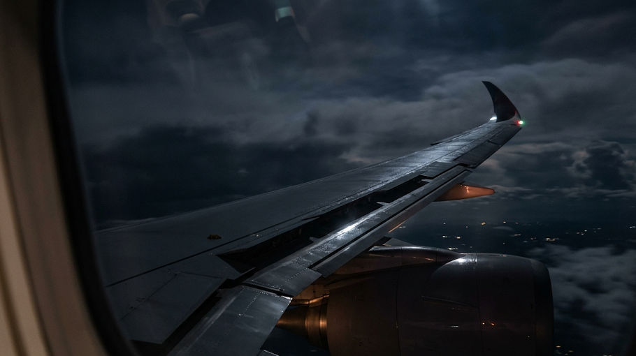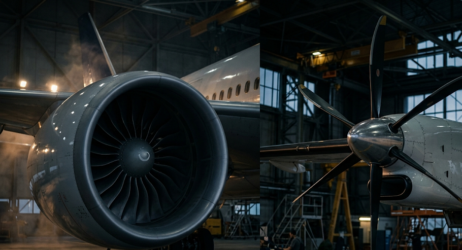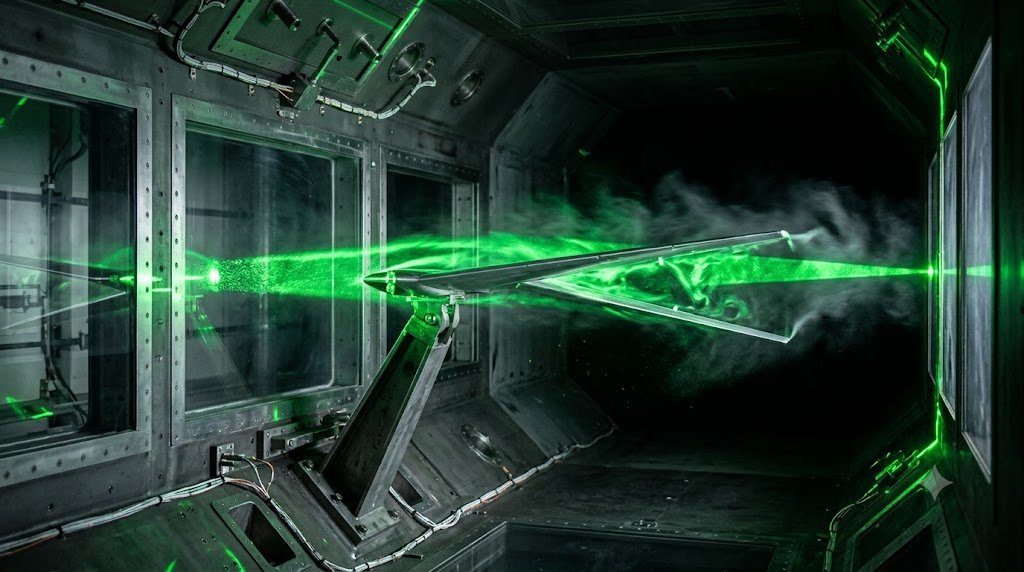
In the structural design of aircraft wings, control surfaces, and empennage assemblies, designing purely for static structural strength is catastrophic if dynamic aeromechanical coupling is ignored. Aircraft wings are flexible elastic bodies that bend and twist under aerodynamic loads. When aerodynamic forces, structural elastic restoring forces, and inertial mass forces interact dynamically, a violent, self-excited aerodynamic instability known as Aeroelastic Flutter can be triggered—an oscillation that can tear a transport wing or tailplane apart within seconds.
The physical science of aeroelasticity is conceptualized via Collar’s Triangle, connecting three fundamental physical forces: Aerodynamic Forces ($A$), Elastic Forces ($E$), and Inertial Forces ($I$). Static aeroelastic phenomena (such as torsional wing divergence and aileron control reversal) connect Aerodynamic and Elastic forces. Dynamic aeroelastic phenomena (classical flutter and buffeting) incorporate Inertial forces, creating unstable coupled multi-degree-of-freedom resonant oscillations.
Classical Bending-Torsion Wing Flutter Dynamics
The most dangerous aerodynamic flutter mode is coupled Two-Degree-of-Freedom Bending-Torsion Flutter. An aircraft wing has two primary natural vibration modes:
- First Bending Mode: The wing tip flexes vertically up and down.
- First Torsional Mode: The wing twists about its elastic axis, altering the local aerodynamic angle of attack ($\Delta \alpha$).
At low airspeeds, both vibration modes are naturally damped by aerodynamic air resistance. However, as airspeed increases toward the Flutter Speed ($V_F$), aerodynamic forces shift the apparent structural stiffness and damping. At the critical flutter speed, the bending and torsional frequencies merge into a single coupled frequency with an unstable 90-degree phase shift: the wing twists upward just as it flexes upward, extracting net kinetic energy from the passing airstream on every oscillation cycle. Amplitude grows exponentially until structural failure occurs.
The Theodorsen Function and Unsteady Aerodynamic Lift
Analyzing dynamic flutter requires calculating aerodynamic lift under rapid harmonic oscillation, modeled via Theodorsen’s Unsteady Aerodynamic Theory. As an aerofoil oscillates, it sheds a continuous planar wake of trailing shed vortices into the airstream behind the trailing edge. These shed vortices induce downwash back onto the aerofoil, altering instantaneous aerodynamic lift magnitude and introducing a phase lag.
Theodorsen introduced the complex function $C(k) = F(k) + i G(k)$, where $k$ is the Reduced Frequency ($k = \omega b / v$). Propulsion and structural aerodynamicists solve the complex flutter eigenvalue equation (the $p-k$ method or $V-g$ method) to ensure that the certified maximum operating limit airspeed ($V_{MO} / M_{MO}$) incorporates a mandatory 20% velocity safety margin (1.20 $V_{D}$) beneath the onset of flutter under FAA Part 25.629.
| Aeroelastic Instability Phenomenon | Governing Coupled Forces | Mathematical Boundary Metric | Primary Structural Countermeasure | Notable Aviation Case |
|---|---|---|---|---|
| Classical Bending-Torsion Flutter | Aerodynamic + Elastic + Inertia | Flutter Speed (V_F) via V-g Method | Mass Balancing Ahead of Elastic Axis | Transonic Flight Flutter Testing |
| Static Torsional Divergence | Aerodynamic + Elastic (Zero Inertia) | Divergence Speed (q_div = K_theta / e·C_L) | Aeroelastic Tailoring (CFRP Layups) | Forward-Swept Wings (X-29) |
| Aileron Control Reversal | Aerodynamic + Elastic Torsion | Reversal Speed (q_rev) | Inboard High-Speed Flaperons | High-Speed Transonic Air transport |
| Transonic Control Surface Buzz | Shockwave Boundary-Layer Separation | Mach Limit-Cycle Oscillation (LCO) | Hydraulic Actuator Stiffening | Supersonic Fighter Aileron Flutter |
Aeroelastic Tailoring: Exploiting Directional Composite Coupling
In forward-swept wing aircraft (such as the experimental Grumman X-29), conventional metals suffer from catastrophic Static Wing Divergence: upward bending causes the wing tips to twist nose-up aerodynamically, increasing lift and bending further until the wing snaps off at low speeds.
Composites solve this through Aeroelastic Tailoring. By orienting carbon-fiber plies asymmetrically relative to the wing spar axis, engineers induce beneficial Bend-Twist Coupling: when the wing flexes upward under a gust, the structural laminate automatically twists the wing nose-down, washing out aerodynamic angle of attack and shedding aerodynamic load passively.
Mass Balancing: Tuning the Center of Gravity of Control Surfaces
Primary flight control surfaces (elevators, ailerons, rudders) are susceptible to catastrophic control surface flutter if their mass center of gravity lies behind their physical hinge line. If the vertical stabilizer flexes left, the trailing-edge rudder lags behind due to rotational inertia, deflecting the rudder and driving aerodynamic forces that amplify tailplane flutter.
Aerospace structures prevent this through Control Surface Mass Balancing. Heavy depleted uranium or tungsten balance weights are mounted on forward-projecting arms ahead of the hinge line, placing the surface CG directly on or slightly ahead of the aerodynamic hinge center, decoupling control surface inertia from airframe structural bending modes.
p-k Method Mathematical Formulations of Unsteady Aerodynamic Flutter Equations
Aeroelastic flutter is an unstable, self-excited structural vibration phenomenon in which aerodynamic forces, structural elastic restoring forces, and inertial forces interact in a destructive feedback loop. As airspeed increases toward the flutter boundary ($V_f$), energy from the surrounding freestream airflow is continuously transferred into structural vibration modes of the wing, vertical fin, or horizontal stabilizer. Left unchecked, amplitude grows exponentially within milliseconds, culminating in catastrophic structural breakup.
To analytically predict the flutter speed and mode coalescence, aerospace aeroelasticity engineers solve the classical p-k Method governing equations in the frequency domain:
[ – M · ω2 + i · ω · C + K – ½ ρ V2 · Q(k, M) ] · { q } = 0
Where $\mathbf{M}$ is the generalized structural mass matrix, $\mathbf{C}$ is structural damping, $\mathbf{K}$ is the structural stiffness matrix, $q$ is the generalized modal coordinate vector, and $\mathbf{Q}(k, M)$ represents the Generalized Aerodynamic Forces (GAF) matrix, which is a nonlinear function of Mach number ($M$) and reduced frequency ($k = \omega b / V$, where $b$ is the aerodynamic semi-chord). Flutter occurs at the critical airspeed where the damping parameter ($g$) of any coalescing mode crosses zero and becomes positive (negative total damping).
In high-aspect-ratio commercial transport wings, classical flutter arises from the aerodynamic coalescence of the fundamental 1st Wing Bending mode and 1st Wing Torsional mode. As airspeed increases, aerodynamic pitch moments shift the apparent torsional stiffness, driving the two separate modal natural frequencies closer together until they merge at the flutter frequency ($\omega_f$). The phase lag between out-of-plane flexural bending and chordwise pitch torsion causes the wing to extract net positive aerodynamic work over each oscillation cycle, driving violent limit cycle oscillations (LCO).
Aeroelastic Tailoring in Carbon Fiber Laminates to Decouple Washin/Washout
Forward-swept wings naturally experience static aeroelastic divergence—where upward aerodynamic lift twists the wing leading edge upward (washin), compounding local angle of attack and lift until the wing tears off. Modern transport wings employ swept-back geometry combined with Aeroelastic Tailoring of composite plies. By orienting carbon fiber layups off-axis relative to the elastic structural axis, engineers intentionally introduce directional bending-torsion coupling. When an aerodynamic gust bends the wingtip upward, the structural coupling automatically forces the wingtip to twist nose-down (washout), dynamically shedding lift and providing passive aerodynamic gust load alleviation.
Flight Test Certification: High-Altitude Flutter Clearance and Explosive Pyrotechnic Bonkers
Airworthiness certification under FAA 14 CFR Part 25.629 mandates that an aircraft must remain completely free from aeroelastic flutter, divergence, and limit cycle oscillations throughout the entire flight envelope up to 1.15 times the Design Dive Speed ($1.15 \times V_D / M_D$). Proving this flutter margin requires dangerous high-altitude flight flutter testing conducted by specialized experimental test pilots and telemetry aeroelasticity engineers.
To actively excite structural vibration modes in flight, prototype test aircraft are fitted with specialized flutter excitation systems: (1) Aerodynamic Flutter Vanes mounted on wingtips that oscillate sinusoidally across discrete frequency sweeps (1 to 30 Hz), (2) Control Surface Chirp Inputs driven through digital fly-by-wire actuator test channels, and (3) Pyrotechnic Flutter ‘Bonkers’—small explosive impulse cartridges mounted along the wing spar that fire micro-second impulsive forces to excite transient structural decaying rings.
During supersonic or high-subsonic test dives, accelerometer arrays along the wings and empennage stream gigabits of vibrational data to telemetry ground stations via microwave links. Ground computers execute real-time Matrix Pencil and Stochastic Subspace Identification (SSI) algorithms to extract structural damping ratios ($\zeta$) for each mode within seconds. If modal damping begins decaying toward zero ($g < 0.03$), the flight test director immediately aborts the dive over the radio to prevent structural loss.
Aeroelastic Control Surface Reversal and High-Speed Roll Performance
At transonic airspeeds, thin flexible swept wings suffer from Aileron Reversal. When an outboard aileron deflects downward to increase lift and roll the aircraft, the aerodynamic trailing-edge pitching moment twists the flexible wing nose-down. If dynamic pressure ($q = \frac{1}{2} \rho V^2$) exceeds the control reversal dynamic pressure ($q_r$), the lift reduction from negative wing twist completely overpowers the lift gain from aileron deflection, causing the aircraft to roll in the opposite direction. Modern airframes eliminate this phenomenon by locking out outboard ailerons at high speed, relying exclusively on high-speed inboard ailerons and roll spoilers.
Ground Vibration Testing (GVT) Protocols and Modal Frequency Validation
Prior to conducting any first flight of a new aircraft type or after substantial structural modifications (such as installing new high-bypass turbofans or aerodynamic winglets), aerospace manufacturers must perform a comprehensive Ground Vibration Test (GVT) under FAA 14 CFR Part 25.629 mandates. The objective of the GVT is to experimentally measure the aircraft’s natural structural vibration modes, natural frequencies, and modal damping ratios to validate and calibrate finite element (FEM) structural dynamic models.
To isolate structural vibration modes from ground boundary conditions, the fully assembled aircraft is suspended on an ultra-soft ‘soft-spring’ pneumatic suspension system (inflated bungee or air-spring rigs) yielding rigid-body suspension frequencies below 1.0 Hz—simulating free-flight boundary conditions. Dozens of electrodynamic shakers are positioned at strategic structural locations (wingtips, engine pylons, horizontal and vertical stabilizers), injecting sinusoidal swept-sine, random, or multi-harmonic force inputs across frequency ranges from 1 to 50 Hz. Hundreds of tri-axial accelerometers measure the aircraft response, providing experimental modal vectors that feed directly into analytical flutter clearance equations.
Mechanically operated or hydraulically boosted control surfaces (elevators, rudders, ailerons) are vulnerable to control-surface flutter if the surface center of gravity (CG) lies behind its mechanical hinge line. Aerodynamic gusts force the wing to bend, causing the trailing edge surface to lag behind due to rotational inertia, aerodynamically amplifying the oscillation. Structural designers install depleted uranium, tungsten, or lead Mass Balance Weights forward of the hinge line, moving the surface CG directly onto or ahead of the hinge line to completely eliminate inertial flutter coupling.
Active Flutter Suppression (AFS) and Morphing Wing Aeroelastic Technology
While historical aircraft design relied exclusively on passive structural stiffness, mass balancing, and aerodynamic geometry to isolate flight envelopes from aeroelastic flutter, next-generation transport aircraft are pioneering Active Flutter Suppression (AFS) and morphing aeroelastic wing structures. By integrating high-bandwidth fly-by-wire control laws with distributed piezoelectric sensors and fast electromechanical actuators, an active aircraft can dynamically suppress flutter oscillations in real time.
When accelerometers along the wing detect the onset of coalescing bending-torsion oscillations, the AFS computer commands high-frequency micro-deflections of trailing-edge control surfaces (flutter suppression flaps or piezoelectric continuous-trailing-edge flaps) out of phase with the structural motion. These micro-deflections generate localized aerodynamic forces that introduce artificial positive damping, actively quenching the aeroelastic vibration before amplitude can grow. Active flutter suppression allows aircraft designers to build lighter, ultra-high-aspect-ratio flexible wings (aspect ratios exceeding 15:1 to 20:1, as seen in the Boeing Transonic Truss-Braced Wing / TTBW concept), slashing induced drag and saving up to 10% in overall cruise fuel burn.
Modern commercial transports (including the Airbus A350 and Boeing 787) integrate certified Gust Load Alleviation (GLA) suites. Dual nose-mounted optical LiDAR sensors or dynamic pressure pitot sensors detect atmospheric gust velocity profiles milliseconds before the turbulence reaches the main wings. The fly-by-wire computers symmetrically deflect outboard ailerons and spoiler panels upward in a fraction of a second, dynamically dumping wing lift and reducing structural wing root bending moments by up to 15%, permitting significant structural airframe weight reductions.
Advanced Aerostructures Architecture: Materials Science, Aeroelasticity and Damage Tolerance
The structural airframe of a commercial transport aircraft represents a high-performance, lightweight pressure vessel engineered to withstand millions of severe fatigue load cycles across decades of commercial service. Aerospace structural engineering balances three competing technical requirements: Structural Weight Minimization, Aeroelastic Dynamic Stability, and Lifelong Damage Tolerance.
The structural design philosophy governing modern airframes encompasses:
- Hybrid Multi-Material Airframe Architecture: Strategic deployment of advanced materials where their physical mechanical properties excel: carbon fiber reinforced polymers (CFRP) for high-strain wing skins, horizontal stabilizers, and pressurized fuselage barrels; ultra-high-strength forged titanium alloys (Ti-6Al-4V) for highly concentrated load transfer points like landing gear truck beams and engine pylon mounts; and fatigue-resistant aluminum-lithium (Al-Li) alloys for internal fuselage frames and wing leading edges.
- Aeroelastic Tailoring and Flutter Margin Clearance: Aligning directional carbon fiber plies off-axis to introduce passive bending-torsion coupling that sheds aerodynamic gust loads automatically, while proving that the airframe remains completely free from self-excited aeroelastic flutter up to 1.15 times design dive speed ($1.15 imes V_D / M_D$) through ground vibration testing and high-speed flight flutter sorties.
- Damage Tolerance and Fracture Mechanics: Codifying FAA 14 CFR Part 25.571 standards by assuming microscopic material flaws exist in all primary joints, and ensuring crack growth rates governed by Paris’ Law are slow enough to guarantee reliable detection during routine non-destructive inspections (NDI) before reaching critical flaw sizes ($a_{crit}$).
Modern aircraft airframes demonstrate how advanced structural engineering preserves passenger safety: from classical laminate theory predicting orthotropic composite strain distributions, to deep-hole gun drilling and shot peening locking residual compressive stresses into titanium forgings, to high-frequency eddy current NDI detecting subsurface rivet lap joint micro-fissures. Structural integrity is the foundational bedrock upon which all aerospace flight operations rely.
Lifelong Structural Airworthiness and MSG-3 Maintenance Program Integration
Airframe structural health is certified through continuous structural maintenance programs formulated under MSG-3 logic. Structural inspection intervals—ranging from line A-checks to comprehensive depot D-checks where fuselages are stripped to bare frames—ensure that environmental corrosion, multi-site fatigue damage, and accidental ramp impacts are systematically identified and repaired in strict accordance with certified Structural Repair Manual (SRM) guidelines, preserving structural airworthiness across 100,000+ flight cycles.