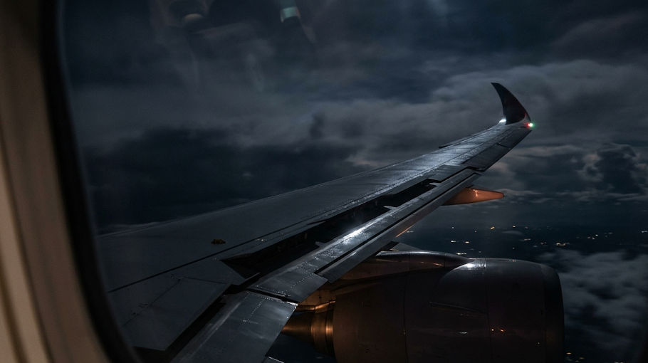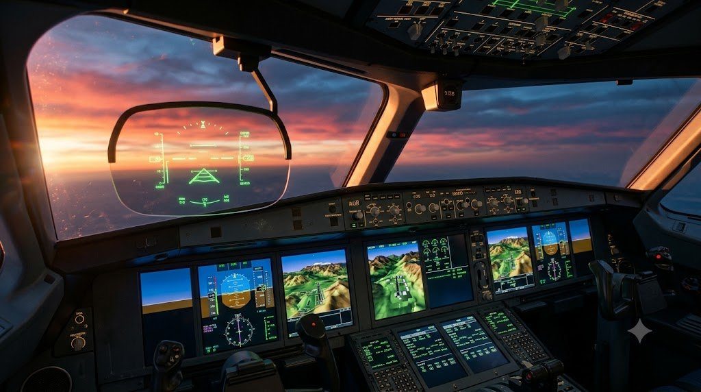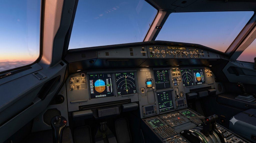
The transition from mechanical flight control cables, pulleys, and pushrods to Fly-by-Wire (FBW) flight control architectures represents one of the most profound evolutionary milestones in civil transport and military aviation. Pioneered in commercial transport by the Airbus A320 and Boeing 777 and advanced in modern widebody aircraft (A350, B787), fly-by-wire replaces heavy hydromechanical control linkages with digital computers and electrical signaling, processing pilot control stick inputs through mathematical Flight Control Laws to command primary flight control surface actuators with dynamic envelope protection.
In a conventional aircraft, pulling the control column back mechanically deflects the elevator by an angle proportional to column displacement ($\Delta \delta_e \propto \Delta x_{stick}$). In a digital fly-by-wire transport, pilot sidestick displacement does not command a surface angle; instead, it commands an aircraft physical response—specifically a Pitch Maneuver Demand ($C^*$ parameter) or Roll Rate ($p$). Flight control computers compute the elevator and spoiler deflections required to achieve that demanded motion while actively monitoring aircraft aerodynamic boundaries to prevent structural overload or stall.
The C* (C-Star) Flight Control Law: Blending Normal Acceleration and Pitch Rate
In the pitch axis, commercial fly-by-wire systems implement the mathematical $C^*$ (C-Star) Control Law, which dynamically blends load factor (normal acceleration, $N_z$) and pitch angular velocity ($q$):
C* = Nz + Vco * q
Where $V_{co}$ is the Crossover Airspeed (typically around 210 to 230 knots). The physical rationale for this dual blending is rooted in human pilot perception across varying flight regimes:
- Low-Speed Flight (Takeoff and Approach): Dynamic pressure is low, so pulling the stick produces significant pitch attitude change ($q$) with modest normal acceleration ($N_z$). The $V_{co} \cdot q$ term dominates, providing precise pitch attitude control for flare and touchdown.
- High-Speed Cruise Flight (Mach 0.85): Dynamic pressure is massive, so modest elevator deflections generate severe g-forces ($N_z$). The normal acceleration term dominates, transforming the sidestick into a direct g-command controller ($1.0 \text{ g}$ neutral stick for level trim flight).
Flight Envelope Protection: Hard vs. Soft Limits
The defining flight safety feature of digital fly-by-wire is automated Flight Envelope Protection. The system continuously cross-checks air data and inertial reference units to prevent the aircraft from exiting its safe aerodynamic operating envelope:
- High-Angle-of-Attack (Alpha) Protection: If the pilot pulls full aft sidestick at low speed, the flight control computers smoothly intercept aerodynamic stall limits (Alpha-Prot). Even if the pilot holds full backward stick, the computer limits angle of attack strictly to Alpha-Max, preventing aerodynamic stall without stick shakers or pushers.
- High-Speed Protection: If the aircraft exceeds maximum operating speed ($V_{MO} / M_{MO}$), the computers pitch the nose up automatically and reduce thrust, preventing supersonic flutter and structural divergence.
- Pitch and Bank Angle Limiting: Bank angles are limited to 33° hands-off (with positive spiral stability) and hard-limited to 67°, preventing accidental aerodynamic roll upsets.
| Flight Control Law Status | Pitch Control Mode | Roll Control Mode | Envelope Protection Active | Reconfiguration Trigger |
|---|---|---|---|---|
| Normal Law | C* Maneuver Demand (1.0g trim) | Roll Rate Demand (p max = 15°/s) | Full Protection (Alpha, Bank, VMO, Load) | All Primary Sensors & Computers Healthy |
| Alternate Law (Reduced) | Load Factor (Nz) Demand | Direct Surface Relationship | Low Speed & High Speed Stability Only | Multiple Dual-Sensor Disagreements |
| Direct Law | Direct Elevator Deflection | Direct Aileron/Spoiler Deflection | None (Conventional Aircraft Response) | Multiple Triple-Computer Failures |
| Mechanical Backup | Pitch Trim Wheel (Cables) | Rudder Pedals (Cables) | None (Pure Mechanical Fallback) | Complete Electrical System Blackout |
Dissimilar Hardware and Software Redundancy: Preventing Common-Cause Faults
To achieve certification under FAA 14 CFR 25.1309 (probability of catastrophic failure less than $10^{-9}$ per flight hour), commercial fly-by-wire architectures deploy Multi-Channel Dissimilar Redundancy (e.g., Airbus ELAC and SEC computers, Boeing PFCs).
Each flight control computer incorporates two distinct hardware sections: a Control Channel and a Monitoring Channel, running dissimilar microprocessor silicon (e.g., Motorola vs. Intel architectures) and programmed by independent software engineering teams using distinct compilers. If internal comparators detect a mathematical divergence between control and monitor channels, that computer disconnects itself in less than 5 milliseconds, seamlessly transferring command to redundant backup computers.
Side-Stick Inceptor Mechanics: Passive vs. Active Feedback
In civil transport fly-by-wire cockpits, pilot control inceptors feature two distinct design philosophies:
- Passive Spring-Centering Sidesticks (Airbus): Fixed mechanical spring gradients with electronic dual-sidestick priority takeover pushbuttons. Sidesticks are not mechanically linked; priority logic alerts the crew if simultaneous dual inputs occur.
- Active Inceptor Systems (Gulfstream G500/G600, B787): Incorporate internal brushless DC electric servo actuators that back-drive the opposite sidestick electronically, providing tactile visual and force cross-cockpit feedback that mirrors pilot control movements identically.
State-Space Mathematical Formulation of C* Flight Control Criteria and Angle-of-Attack Limiting
In modern digital fly-by-wire (FBW) commercial aircraft, pilot sidestick or control column deflections do not represent direct mechanical commands to control surface actuators. Instead, flight control computers (FCCs) interpret pilot inputs as demands for commanded aircraft dynamic parameters. In the longitudinal pitch axis, the foundational control parameter utilized in Airbus, Boeing, and Embraer FBW architectures is the $C^*$ (C-Star) Handling Qualities Criterion, which blends pitch rate ($q = \dot{\theta}$) and pilot-station normal acceleration ($n_z$) into a unified feedback metric:
C* = nz + (Vco / g) · q
Where $V_{co}$ represents the crossover velocity (typically chosen between $120 \text{ m/s}$ and $150 \text{ m/s}$ / approximately 230 to 290 knots calibrated airspeed), and $g$ is the acceleration of gravity ($9.80665 \text{ m/s}^2$). At low flight velocities (takeoff, approach, and landing), the $V_{co} \cdot q$ term dominates, causing the aircraft to respond cleanly as a direct pitch rate demand machine—providing precise, intuitive attitude control during flare and touchdown. At high cruise speeds, normal load factor ($n_z$) dominates, making the aircraft behave as a load factor demand system that automatically trims for speed and prevents structural over-g maneuvers regardless of pilot input magnitude.
Under Normal Law, the FCCs implement active hard protection boundaries: (1) Angle-of-Attack (AoA) Protection limits aircraft attitude to $\alpha_{prot}$ and $\alpha_{max}$, preventing aerodynamic wing stall even if the sidestick is held at full aft deflection; (2) High-Speed Protection automatically pitches the nose up if airspeed exceeds Maximum Operating Velocity/Mach ($V_{MO} / M_{MO}$); (3) Pitch Attitude Protection caps pitch limits to $+30^\circ$ nose-up and $-15^\circ$ nose-down; and (4) Bank Angle Protection restricts roll angle to $67^\circ$, automatically returning to $33^\circ$ when the stick is released.
Dissimilar Hardware Redundancy and Asynchronous Microprocessor Diversity
To eliminate Common Mode Failures (CMF) where software compiler anomalies or silicon processor errata could simultaneously disable all flight controls, FBW flight control suites incorporate dissimilar multi-computer redundancy. In the Airbus A320/A350 architecture, flight control is distributed across primary Flight Control Primary Computers (FCPC / ELAC) and secondary Flight Control Secondary Computers (FCSC / SEC). Each computer contains two physically and logically separate internal units: a Command Computer and a Monitor Computer, programmed by independent engineering teams using completely separate compiler chains running on dissimilar microprocessors (e.g., Intel architecture versus Motorola / PowerPC architecture).
In-Flight Incident Analysis: Qantas Flight 72 Air Data Inertial Reference Unit (ADIRU) Anomaly
On October 7, 2008, Qantas Flight 72 (an Airbus A330-300 flying from Singapore to Perth) was cruising smoothly at 37,000 feet when Air Data Inertial Reference Unit Number 1 (ADIRU 1) experienced an internal single-event upset (microprocessor memory corruption). The corrupted ADIRU began transmitting spurious, intermittent spikes in Angle of Attack (AoA), suddenly reporting that the aircraft’s angle of attack was $+50^\circ$, when the aircraft was actually in stable level flight at $+2^\circ$ AoA.
Because of a subtle architectural logic vulnerability in the flight control primary computer (FCPC) sensor-filtering algorithm, these brief AoA spikes bypassed the rejection filter. The FBW computers concluded the aircraft was about to enter an aerodynamic stall, triggering Normal Law Alpha Protection. The flight control computers commanded an abrupt, uncommanded nose-down elevator deflection, pitching the aircraft down violently at $-0.8 g$ and injuring passengers in the cabin. The flight crew promptly disconnected autopilot and stabilized the aircraft, executing an emergency landing at Learmonth.
The Australian Transport Safety Bureau (ATSB) investigation resulted in global software updates across Airbus FBW aircraft. The revised algorithm enforces multi-sample consistency checking: if an AoA sensor reading changes faster than the maximum physical pitch acceleration of the airframe, the spike is discarded as an electrical glitch. Furthermore, if two independent AoA sensors disagree by more than $5.5^\circ$, the system automatically sheds Normal Law and degrades gracefully to Alternate Law, returning manual pitch authority to the pilot.
The Degradation Cascade: Normal Law to Alternate Law and Direct Law
Modern fly-by-wire flight control architectures feature tiered degradation levels designed to keep the aircraft fully controllable under multiple failures: (1) Normal Law (full C* feedback and envelope protection active), (2) Alternate Law (C* load factor demand remains, but AoA stall and bank angle protections are replaced with standard audio stall warnings), (3) Direct Law (elevator and aileron deflections become directly proportional to sidestick displacement, exactly like a conventional aircraft), and (4) Mechanical Backup (rudder pedals and horizontal stabilizer pitch trim wheels maintain mechanical cable links for core survivability).
Flight Control Actuator Rigging, LVDT Calibration and Automated Pre-Flight BIT Testing
Primary flight control surfaces (ailerons, elevators, rudder) driven by digital fly-by-wire commands require absolute physical positioning accuracy to maintain certified handling qualities. Actuator assemblies incorporate dual tandem hydraulic cylinders powered by separate hydraulic systems, controlled by dual electro-hydraulic servo valves (EHSV) and monitored by multi-channel Linear Variable Differential Transformers (LVDT). During heavy maintenance C-Checks, technicians perform mechanical and electronic rigging using computerized rigging pin fixtures and digital clinometers, ensuring surface deflection angles match FCC commands within $\pm 0.05$ degrees of arc.
Every time power is applied to the aircraft prior to departure, the flight control computers execute an autonomous Power-Up Built-In Test (PBIT) and hydraulic pressurization test. The FCCs cycle control surface actuators through micro-movements, injecting small electrical test pulses into servo torque motors to measure dynamic response latency, coil impedance, and hydraulic spool travel rate. If an actuator exhibits excessive fluid leakage slippage or slow response time ($> 40 \text{ ms}$ lag), the computer annunciates a flight control fault, preventing flight dispatch under Master Minimum Equipment List (MMEL) guidelines.
In fly-by-wire flight decks without mechanical cable linkages, pilot sidesticks incorporate sophisticated electromechanical Active Feel Units (AFU). Unlike passive spring dampers, modern active sidesticks utilize digital torque motors to synthesize artificial tactile force gradients. The control laws dynamically increase stick resistance as aircraft airspeed increases, providing pilots with intuitive physical tactile feedback that discourages over-controlling at high aerodynamic dynamic pressures.
Future Horizons: Adaptive Neural Flight Control and Autonomous Pilotless Systems
The continuous evolution of fly-by-wire flight control architectures is pointing toward Adaptive Flight Control Systems (AFCS) and intelligent autonomous trajectory management. In experimental NASA and defense flight test programs (such as the F-15 ACTIVE and X-62A VISTA), adaptive neural network controllers have demonstrated the ability to dynamically reconfigure flight control laws in real time following severe battle damage or primary structural failure (such as the loss of half a wing or severed tail surfaces). By continuously identifying online aerodynamic stability derivatives, the adaptive system learns how to control the crippled airframe using remaining operational control surfaces and differential engine thrust.
For commercial civil transport aviation, next-generation fly-by-wire suites are paving the way for Single-Pilot Operations (SPO) and autonomous emergency recovery systems. Advanced envelope protection suites integrate ground collision avoidance algorithms (Auto-GCAS) and automated emergency descent modes (AEDM): if flight crew members lose consciousness due to sudden cabin depressurization, the flight control computers autonomously disconnect normal guidance, roll into a $90^\circ$ emergency bank, deploy flight spoilers, descend rapidly to 10,000 feet, and execute an autonomous autoland approach to the nearest suitable airport.
EASA is establishing formal airworthiness certification frameworks for Extended Minimum Crew Operations (eMCO), enabling a single pilot in the cockpit during cruise flight while the second pilot rests. Certification mandates ultra-resilient fly-by-wire redundancy, real-time pilot physiological monitoring (eye-tracking and cardiac sensors), and AI-driven co-pilot virtual assistants certified to DO-178C Level A standards.
Integrated Aircraft Systems Engineering: Fly-By-Wire, High-Pressure Hydraulics and Pneumatics
The design, certification, and airworthiness operation of modern transport category aircraft depend upon the seamless physical and logical integration of Flight Control Systems, Hydraulic Power Distribution, Environmental Control Systems, and Automated Flight Guidance. These mission-critical architectures function as an interconnected physiological nervous system within the airframe, transforming pilot intent and sensor telemetry into precise aerodynamic control forces.
Modern aircraft systems architecture is defined by three fundamental design tenets:
- Dissimilar Multi-Channel Redundancy: Eliminating single-point and common-mode failure vulnerabilities through quad-redundant flight control computers, dual dissimilar microprocessor architectures, and triple independent 3,000/5,000 psi hydraulic power distribution circuits routed through segregated airframe zones.
- Dynamic Energy Management: Optimizing secondary power extraction from engine cores. The progressive adoption of More-Electric Aircraft (MEA) architectures replaces inefficient engine bleed air with high-voltage 230V AC electric generators and localized Electro-Hydrostatic Actuators (EHA), reducing aircraft empty weight and slashing fuel consumption.
- Envelope Protection and Human Factors Integration: Ensuring flight control laws (such as C* pitch rate and normal load factor demand) establish insurmountable safety boundaries—preventing structural over-g excursions, aerodynamic stalls, and overspeed flutter regardless of pilot stick deflections during high-stress operational upsets.
A commercial airliner cannot execute a successful Category IIIb autoland approach without the coordinated synergy of its flight systems: the FMS calculates the navigation trajectory, the autopilot translates flight path errors into C* control law commands, the FBW computers signal electro-hydraulic servo valves, the 5,000 psi hydraulic circuits deflect primary control surfaces, and the environmental control system maintains cabin differential pressure and thermal comfort. The flawless interoperability of these systems represents the pinnacle of aerospace engineering safety.
System-Level Fault Tolerance, Master Minimum Equipment Lists (MMEL) and Dispatch Reliability
Commercial airline economics depend heavily on on-time departure reliability governed by FAA/EASA certified Master Minimum Equipment Lists (MMEL). The built-in redundancy of modern flight control computers, hydraulic power loops, and cabin air cycle packs enables aircraft to operate safely under designated Category A, B, and C dispatch deferrals—ensuring that transient component faults can be safely addressed during scheduled overnight depot maintenance rather than causing costly terminal gate flight cancellations.