Deflecting primary flight control surfaces (ailerons, elevators, rudders) and deploying heavy landing gear assemblies on commercial transport airliners cruising at transonic speeds demands extraordinary mechanical power. Under aerodynamic dynamic pressures ($q = \frac{1}{2} \rho v^2$) exceeding 15 to 25 kPa, aerodynamic hinge moments acting on an elevator can easily exceed 40,000 to 70,000 Newton-meters. Modern aircraft fulfill these immense force demands via high-pressure Hydraulic Power Distribution Systems and cutting-edge Electro-Hydrostatic Actuators (EHA).
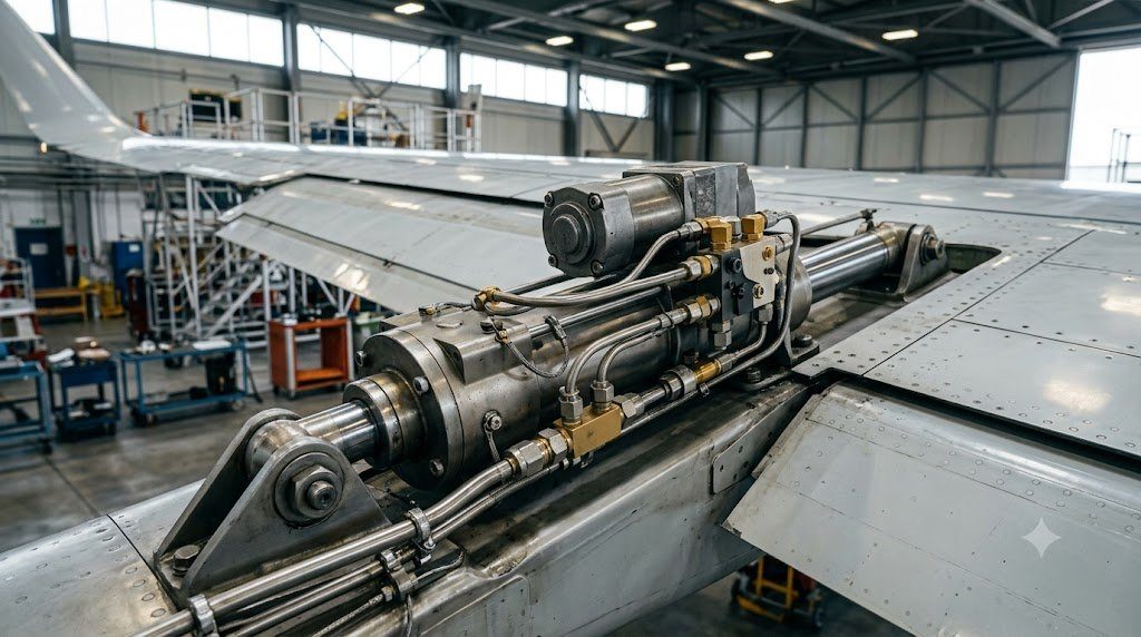
Aircraft hydraulic systems operate under extreme hydrostatic pressures: traditional commercial aircraft operate at 20.7 MPa (3,000 psi), while advanced widebodies (Airbus A380, A350, Boeing 787) have elevated pressure to 34.5 MPa (5,000 psi). By raising system pressure by 67%, the volumetric cross-sectional area of hydraulic actuator cylinders and tubing is reduced proportionally for the same output force ($F = P \cdot A$), shaving upwards of 1,000 to 1,500 kilograms of structural plumbing mass from a long-range airframe.
System Architecture: Independent Color-Coded Hydraulic Circuits
Commercial transport airliners maintain complete hydraulic segregation by partitioning aircraft power into two or three completely independent circuits (universally color-coded as Blue, Green, and Yellow in Airbus aircraft, or Left, Center, and Right in Boeing aircraft). There is zero physical fluid cross-mixing between circuits.
Each circuit is pressurized by multiple independent hydraulic sources:
- Engine-Driven Pumps (EDP): High-displacement variable-displacement axial piston pumps mounted on the engine accessory gearbox, supplying continuous fluid flow up to 140 to 180 liters per minute.
- Electric Motor-Driven Pumps (ACMP): Powered by 115V AC aircraft electrical buses for ground operation and flight backup.
- Power Transfer Unit (PTU): A bi-directional mechanical motor-pump coupling that transfers hydraulic pressure from one circuit to another without transferring a single drop of fluid.
- Ram Air Turbine (RAT): A deployable emergency propeller dropped into the airstream to power an emergency hydraulic pump in the event of total engine flameout.
Electro-Hydrostatic Actuators (EHA) and Electrical Backup Actuators (EBHA)
In the transition toward ‘More Electric Aircraft’ (MEA), modern airframes are progressively replacing centralized hydraulic tubing networks with localized Electro-Hydrostatic Actuators (EHA). An EHA is an autonomous, self-contained hydraulic machine comprising a high-speed brushless DC electric motor, a miniature bi-directional variable-displacement hydraulic pump, an internal fluid reservoir, and a hydraulic actuator cylinder—all packaged directly inside the flight surface hinge bay.
The aircraft routes only electrical power cables (230V AC or ±270V DC) and digital flight control communication buses to the actuator, completely eliminating thousands of meters of leaky hydraulic pipes running through wings and fuselage. In Electrical Backup Hydraulic Actuators (EBHA), the unit operates on standard centralized hydraulics during normal flight, switching autonomously to internal electric-hydraulic mode if central pressure is lost.
| Hydraulic Power System | Nominal Pressure | Working Fluid Type | Weight Scaling Factor | Primary Production Application |
|---|---|---|---|---|
| Standard Commercial 3,000 PSI | 20.7 MPa (3,000 psi) | Phosphate Ester (Skydrol LD-4 / 5) | Baseline (1.00x Mass) | Airbus A320, Boeing 737 / 777 |
| Advanced Commercial 5,000 PSI | 34.5 MPa (5,000 psi) | Type V High-Thermal Skydrol | 0.70x Tubing & Actuator Mass | Airbus A380, A350, Boeing 787 |
| Military High-Performance 5,000 PSI | 34.5 MPa (5,000 psi) | Synthetic Hydrocarbon (MIL-PRF-83282) | Ultra-Compact / High Slew Rate | F-22 Raptor, F-35 Lightning II |
| Electro-Hydrostatic Actuator (EHA) | Local Self-Contained Pressure | Internal Sealed Synthetic Fluid | Eliminates Centralized Tubing | Airbus A380 / A350 Backup Surfaces |
Hydraulic Fluid Rheology: Phosphate Ester Synthetics (Skydrol) vs. Flammability
Early aviation utilized petroleum-based mineral oils (MIL-PRF-5606), but catastrophic aircraft fires caused by high-pressure hydraulic mist spraying onto scorching hot engine exhaust manifolds or brake rotors led to the development of fire-resistant Phosphate Ester Synthetic Hydraulic Fluids (e.g., Skydrol 500B-4 and Skydrol LD-4).
Phosphate ester fluids possess an exceptionally high autoignition temperature exceeding 500°C (932°F). However, they are chemically aggressive: Skydrol dissolves standard nitrile and neoprene rubber seals instantly, demanding specialized Ethylene Propylene Diene Monomer (EPDM) or fluorocarbon (Viton) elastomers. Furthermore, phosphate ester fluids are hygroscopic, reacting with atmospheric moisture to form corrosive phosphoric acid that must be continuously monitored via laboratory acid-number titration.
Actuator Cavitation and Squeeze-Film Hydrodynamic Flutter Suppression
When primary flight control surfaces are subjected to violent aerodynamic turbulence gusts, high-speed fluid velocity through internal servo valve metering orifices can cause localized pressure to drop beneath the vapor pressure of the fluid. The resulting Hydraulic Cavitation collapses fluid vapor bubbles against metal valve lands with intense micro-jets exceeding 1,000 MPa, pitting valve spools.
Modern actuators incorporate anti-cavitation check valves and hydraulic squeeze-film dampers. These dampers absorb aerodynamic gust energy, preventing uncommanded surface flutter and protecting delicate flight control hinge bearings from structural dynamic fatigue.
High-Pressure Fluid Dynamics, Bulk Modulus Cavitation and Electro-Hydrostatic Actuator (EHA) Physics
Commercial transport category aircraft utilize centralized hydraulic systems operating at nominal working pressures of 3,000 psi (20.7 MPa) or 5,000 psi (34.5 MPa, adopted on the Airbus A380 and Boeing 787). Increasing system working pressure from 3,000 psi to 5,000 psi allows a direct 40% reduction in hydraulic fluid volumetric flow rate for equivalent mechanical power transmission ($Power = P \cdot Q$). This reduction permits smaller tubing diameters, downsized piston actuators, and decreased fluid reservoir volumes, yielding an aircraft empty weight reduction exceeding 1,000 kg on ultra-large airframes.
However, operating at 5,000 psi introduces severe fluid dynamic challenges governed by the Effective Bulk Modulus ($\beta_{eff}$) of aviation hydraulic fluid (phosphate ester synthetic fluid, such as Skydrol LD-4 or HyJet V):
βeff = – V · (∂P / ∂V) ≈ 1.4 × 10⁹ Pa · [ 1 + εair · (P0 / P)1/γ ]-1
Under severe pressure drops across servo valve orifices, dissolved air (typically 8% to 10% by volume in unpressurized reservoirs) nucleates out of solution, causing acoustic cavitation, severe acoustic noise, and microscopic erosion pits on servo spool metering lands. Hydraulic return circuits must maintain continuous reservoir pressurization (typically 50 to 60 psig using engine bleed air) to prevent cavitation during high-altitude cruise where ambient pressure drops below 3 psi.
Modern More-Electric Aircraft (MEA) architectures integrate autonomous Electro-Hydrostatic Actuators (EHA) directly at control surface hinge points. An EHA eliminates centralized hydraulic supply tubing, containing its own brushless DC electric motor, reversible axial piston pump, and sealed internal oil reservoir. Under electrical command, the motor drives the local pump to deliver hydraulic pressure directly to the actuator piston, providing localized, fail-passive flight control power backed by the aircraft’s 230V AC electrical distribution bus.
Thermal Dissipation Management in Closed-Loop Hydraulic Distribution Systems
Because hydraulic pumps operate continuously at high volumetric delivery, flow recirculation across pressure relief valves and internal leakage clearances converts mechanical shaft power into hydraulic fluid heat. Hydraulic fluid operating temperature must be strictly maintained between $40^\circ\text{C}$ and $90^\circ\text{C}$; temperatures exceeding $110^\circ\text{C}$ accelerate thermal fluid oxidation, degrade elastomeric ethylene-propylene-diene (EPDM) O-ring seals, and decrease fluid viscosity, causing internal leakage slippage. Aircraft incorporate dedicated fuel-hydraulic heat exchangers installed within wing fuel tanks to continuously reject hydraulic thermal energy into cold fuel supplies.
Investigation Analysis: United Airlines Flight 232 Engine Disintegration and Hydraulic Fluid Depletion
On July 19, 1989, United Airlines Flight 232 (a McDonnell Douglas DC-10-10) suffered a catastrophic titanium disk failure in its tail-mounted Number 2 General Electric CF6-6D engine while cruising at 37,000 feet over Iowa. High-energy titanium fragments severed all three independent hydraulic systems (System 1, System 2, and System 3) which converged in the horizontal tail structure. Over the following 40 seconds, high-pressure hydraulic fluid depleted completely through the sheared lines, leaving the flight crew with zero flight control surface actuators (no ailerons, elevators, rudder, spoilers, or flaps).
The flight crew achieved unprecedented partial directional and pitch control by modulating asymmetric thrust between the two remaining wing engines (differential throttle control), guiding the crippled aircraft to Sioux City airport and saving 184 lives. The NTSB investigation revolutionized aircraft hydraulic architecture, demonstrating that physical segregation and independent power routing alone were insufficient if all circuits traversed common structural pinch points.
Modern transport aircraft incorporate autonomous Hydraulic Velocity Fuses and Priority Valves throughout distribution circuits. If an uncontained fragment severs a downstream line, the sudden massive fluid flow triggers the hydraulic fuse, which snaps shut mechanically to isolate the ruptured branch. This preserves hydraulic fluid volume and system pressure for the remaining critical control surfaces. Furthermore, modern airframes route hydraulic circuits through physically separated airframe quadrants (left fuselage floor, right wing leading edge, keel beam), guaranteeing that no single structural impact can compromise all systems.
Ram Air Turbine (RAT) Aerodynamic Deployment and Emergency Standby Power
In the event of total dual-engine flameout or all-engine electrical generator failure, transport aircraft automatically deploy a Ram Air Turbine (RAT). Spring-loaded actuators eject a two-bladed or four-bladed air turbine into the external supersonic or subsonic freestream. The spinning propeller drives a variable-displacement hydraulic pump (and/or 400 Hz electrical generator), delivering 3,000 psi hydraulic pressure to primary flight controls (elevators, rudder, and ailerons) to ensure controlled descent down to touchdown speed.
Hydraulic Fluid Particulate Contamination Counting (NAS 1638 / ISO 4406) and Sampling
In high-pressure aircraft hydraulic systems operating at 3,000 to 5,000 psi, fluid cleanliness is paramount. Microscopic particulate contaminants—generated by pump piston mechanical wear, seal erosion, or maintenance fluid handling—can bridge ultra-tight servo valve spool clearances ($1.5$ to $3.0 \ \mu\text{m}$), causing spool sticking, valve erosion, and uncommanded control surface hardovers. Aircraft Maintenance Manuals mandate periodic hydraulic fluid sampling analyzed against NAS 1638 or ISO 4406 cleanliness standards.
Fleet airworthiness standards require hydraulic systems to maintain fluid cleanliness at or better than NAS Class 6 (or ISO 17/15/12). Aircraft return circuits incorporate 3-micron absolute micro-fiberglass filter elements equipped with visual and electrical differential pressure indicators ($\Delta P$). If a filter element becomes clogged with particulate debris, the differential pressure indicator pops out a red visual indicator button before the internal bypass valve can open, preventing contaminated fluid from bypassing filtration into downstream flight control servo valves.
Whenever a hydraulic line or component is replaced, maintenance technicians must perform rigorous hydraulic system bleeding to purge entrained air bubbles. Trapped air severely reduces effective fluid bulk modulus, turning hydraulic lines into spongy, compressible fluid springs. Technicians connect ground hydraulic power carts, pressurize the system, and cycle all flight control surfaces through 50 full-stroke sweeps while bleeding fluid through high-point bleed valves until bubble-free laminar oil emerges.
The More-Electric Aircraft (MEA) Revolution and Hydraulic Architecture Elimination
The overarching technological trajectory of commercial aerospace flight systems is the progressive replacement of centralized pneumatic and hydraulic distribution systems with high-voltage electrical power distribution—an engineering paradigm known as the More-Electric Aircraft (MEA). While traditional transport aircraft utilize massive hydraulic pump circuits driven by engine accessory gearboxes, platforms like the Boeing 787 and Airbus A350 have initiated the phased retirement of centralized hydraulics in favor of hybrid electro-hydraulic and electro-mechanical systems.
In a full ‘All-Electric Aircraft’ architecture, centralized 3,000/5,000 psi hydraulic loops are completely eliminated. Control surfaces are actuated exclusively by Electro-Mechanical Actuators (EMA) and self-contained Electro-Hydrostatic Actuators (EHA) powered by high-voltage AC (230V AC) and DC ($\pm 270 ext{V DC}$) electrical buses. Eliminating hydraulic pipes, reservoirs, and fluid saves thousands of kilograms of dead airframe weight, completely eradicates fluid leakage and fire hazards, and slashes line maintenance turn-around times by eliminating hydraulic fluid bleeding and filter replacement protocols.
The primary airworthiness certification challenge preventing immediate universal adoption of pure Electro-Mechanical Actuators (EMA) on primary flight surfaces (ailerons and elevators) is the risk of mechanical screw jam. If a high-speed ball-screw or planetary roller-screw mechanism suffers localized spalling, the actuator can seize mechanically, locking the control surface at an uncontrollable angle. Advanced aerospace EMAs incorporate mechanical pyrotechnic disconnect clutches and fault-tolerant redundant quad-channel brushless DC electric motors to achieve fail-safe free-floating disengagement.
Integrated Aircraft Systems Engineering: Fly-By-Wire, High-Pressure Hydraulics and Pneumatics
The design, certification, and airworthiness operation of modern transport category aircraft depend upon the seamless physical and logical integration of Flight Control Systems, Hydraulic Power Distribution, Environmental Control Systems, and Automated Flight Guidance. These mission-critical architectures function as an interconnected physiological nervous system within the airframe, transforming pilot intent and sensor telemetry into precise aerodynamic control forces.
Modern aircraft systems architecture is defined by three fundamental design tenets:
- Dissimilar Multi-Channel Redundancy: Eliminating single-point and common-mode failure vulnerabilities through quad-redundant flight control computers, dual dissimilar microprocessor architectures, and triple independent 3,000/5,000 psi hydraulic power distribution circuits routed through segregated airframe zones.
- Dynamic Energy Management: Optimizing secondary power extraction from engine cores. The progressive adoption of More-Electric Aircraft (MEA) architectures replaces inefficient engine bleed air with high-voltage 230V AC electric generators and localized Electro-Hydrostatic Actuators (EHA), reducing aircraft empty weight and slashing fuel consumption.
- Envelope Protection and Human Factors Integration: Ensuring flight control laws (such as C* pitch rate and normal load factor demand) establish insurmountable safety boundaries—preventing structural over-g excursions, aerodynamic stalls, and overspeed flutter regardless of pilot stick deflections during high-stress operational upsets.
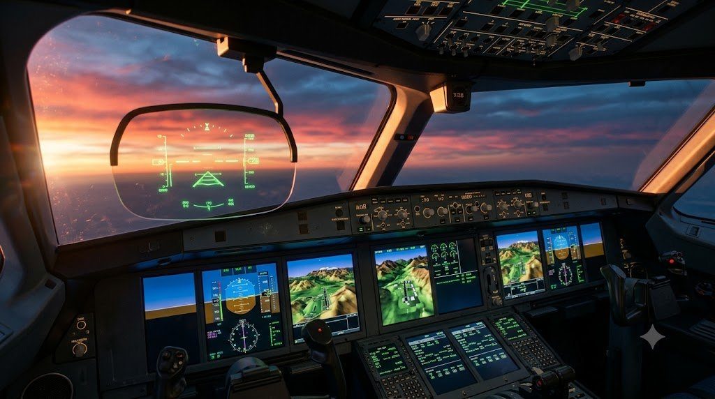
A commercial airliner cannot execute a successful Category IIIb autoland approach without the coordinated synergy of its flight systems: the FMS calculates the navigation trajectory, the autopilot translates flight path errors into C* control law commands, the FBW computers signal electro-hydraulic servo valves, the 5,000 psi hydraulic circuits deflect primary control surfaces, and the environmental control system maintains cabin differential pressure and thermal comfort. The flawless interoperability of these systems represents the pinnacle of aerospace engineering safety.
System-Level Fault Tolerance, Master Minimum Equipment Lists (MMEL) and Dispatch Reliability
Commercial airline economics depend heavily on on-time departure reliability governed by FAA/EASA certified Master Minimum Equipment Lists (MMEL). The built-in redundancy of modern flight control computers, hydraulic power loops, and cabin air cycle packs enables aircraft to operate safely under designated Category A, B, and C dispatch deferrals—ensuring that transient component faults can be safely addressed during scheduled overnight depot maintenance rather than causing costly terminal gate flight cancellations.